
Overview
- Primary topic
- Glass balustrade
- Engineering basis
- Barrier load
- Review status
- Project-specific verification required
Bottom-Clamped Support
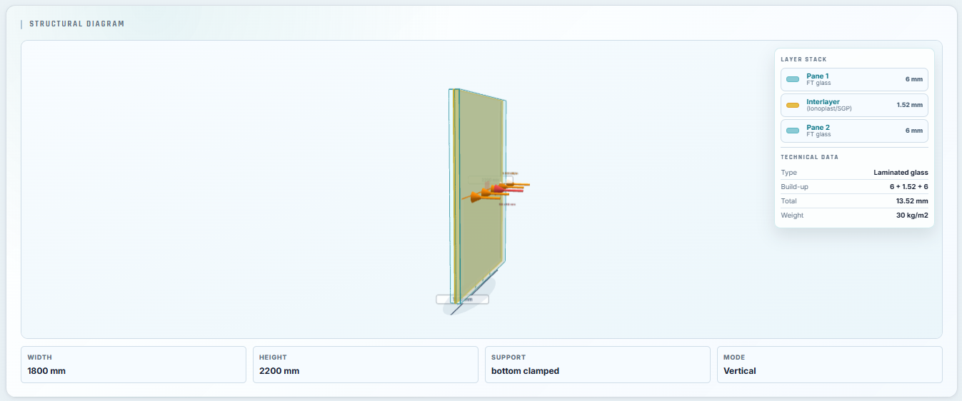
The pane is modelled with its bottom edge clamped and its top and side edges free. This support condition uses the single-pane FEM route rather than the four-edge EN 16612 plate route.
Barrier Actions
The run activates 0.50 kN/m line load, 0.50 kN/m² area load and 0.25 kN point load. The point action is applied at the 1100 mm barrier height on a 1000 × 1200 mm pane.
Engineering Review
Governing Result
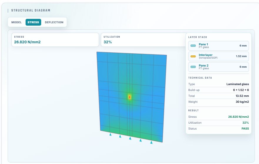
The barrier line action governed both limit states. ULS stress was 3.425 N/mm² with 0.040 utilization, while SLS deflection was 8.792 mm against the displayed 18.462 mm limit.
FEM Review Warning
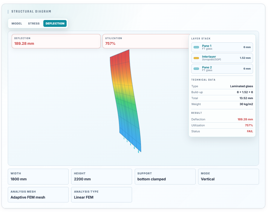
The linear FEM run reported deflection greater than heq;w/2. VitraLab therefore identifies the linear result as conservative and recommends nonlinear FEM for final verification.
Project Basis
Final balustrade design must include the applicable loading rules, fixing-system stiffness and resistance, post-breakage requirements, support details, edge conditions and project specification.
Worked Example: Balustrade 12 / 1.52 / 12
The example documents one software run and does not validate a complete balustrade system.
- Pane size
- 1000 × 1200 mm
- Orientation and support
- Vertical, bottom edge clamped
- Build-up
- 12 + 1.52 + 12 laminated glass
- Glass and interlayer
- Toughened float glass, Family 1 PVB
- Barrier actions
- 0.50 kN/m line, 0.50 kN/m² area, 0.25 kN point
- Load application
- 1100 mm height; point at barrier height
- Governing combination
- 1.5 Barrier Line
- Design action
- 0.750 kN/m
- Calculated response
- 3.425 N/mm² stress
- Utilization or ratio
- 0.040 utilization
- Governing combination
- Barrier Line
- Design action
- 0.500 kN/m
- Calculated response
- 8.792 mm deflection
- Utilization or ratio
- 0.476 of 18.462 mm limit
Linear FEM was conservative because the deflection exceeded h_eq,w/2. Nonlinear FEM and the complete fixing system require final project verification.
Example Barrier Line Load Checks
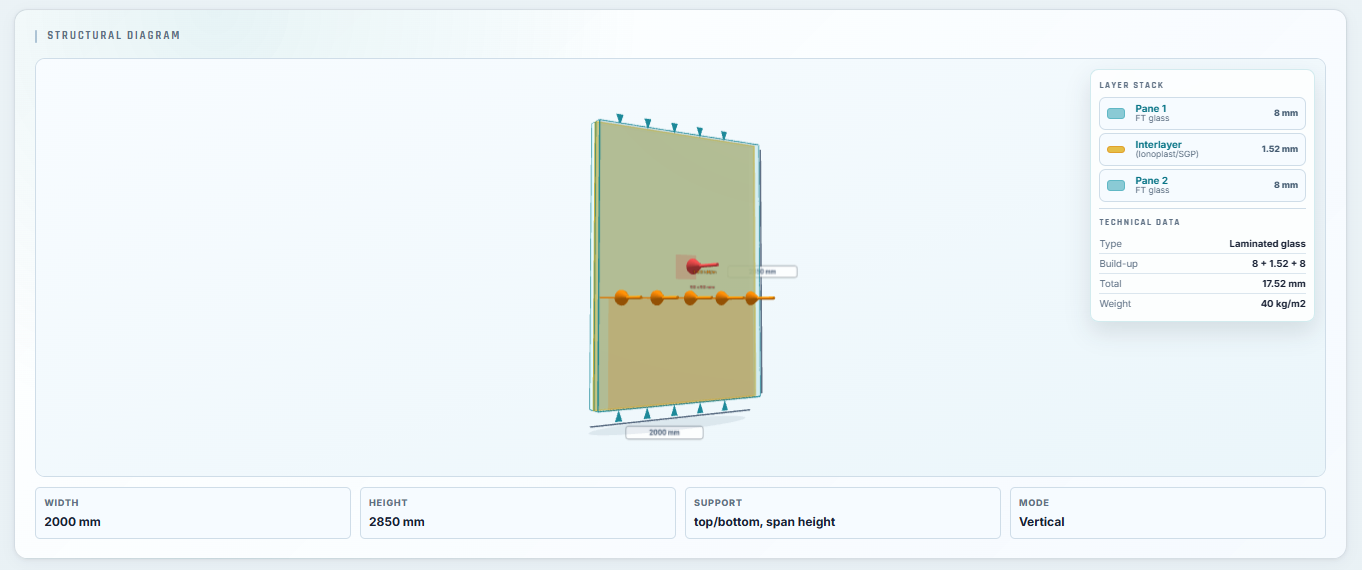
Example VitraLab diagrams and results for one-edge supported and two-edge supported glass under barrier load.
Swipe horizontally to view more figures
Frequently Asked Questions
Why does the bottom-clamped pane use FEM?
One-edge and two-edge supported single panes use the VitraLab FEM route because their response differs from a pane supported continuously on four edges.
Why did the barrier line load govern this example?
For the stated pane, support and action values, the line load produced the highest ULS utilization and SLS deflection ratio.
Does the pane result verify the complete balustrade?
No. Fixings, base shoe or clamps, post-breakage behaviour, edge quality, support stiffness and the applicable project rules require separate verification.
Engineering content is prepared and maintained by VitraLab Engineering. Worked examples show how the current calculator treats a defined case; they do not replace project-specific verification.