
Overview
- Primary topic
- Eurocode 10
- Engineering basis
- prEN 19100-2
- Review status
- Project-specific verification required
What Annex C Addresses
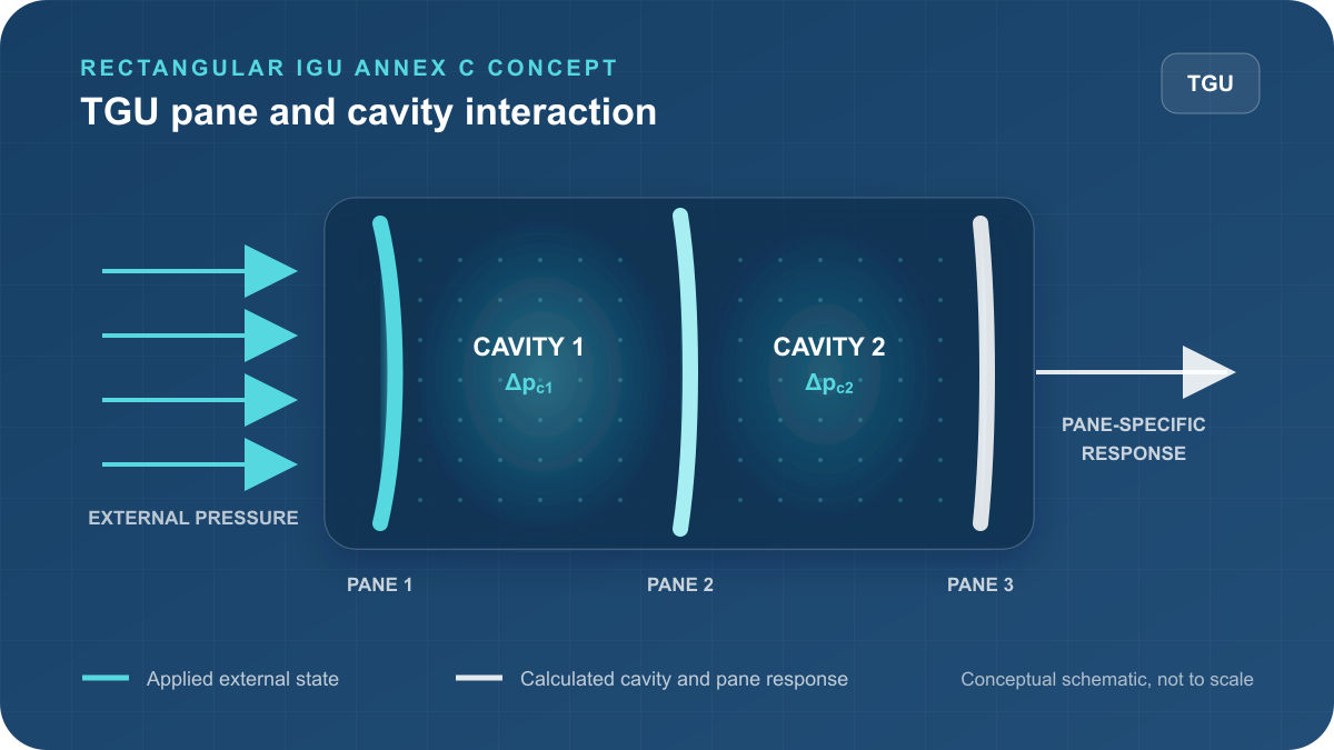
An insulating glass unit is not a collection of independent panes. Changes in external pressure, pane deformation and cavity conditions interact. Annex C provides the basis used by VitraLab to determine how the applied state is shared between the panes and sealed cavities of a rectangular DGU or TGU.
DGU and TGU System Definition
A DGU contains two panes and one cavity. A TGU contains three panes and two cavities. VitraLab defines every pane independently, including monolithic or laminated build-up, while retaining the complete pane-cavity sequence for the system calculation.
Annex C Method
Mechanical Actions
Wind, barrier, maintenance and accidental actions can be entered in the EC10 calculator. The Annex C calculation distributes pressure between the cavities and panes, then passes the resulting pane-specific actions to the structural calculation. ULS and SLS results are assessed for every pane rather than assuming in advance which one governs.
Cavity Reference Conditions
The sealing absolute pressure, sealing temperature and cavity width form part of the IGU reference state. These inputs remain editable because manufacturing, altitude and project conditions can differ. Both TGU cavities use the reported sealing reference while retaining their individual cavity widths.
Altitude and Barometric Pressure
An optional installation-altitude or pressure state represents a difference between sealing pressure and installation ambient pressure. VitraLab reports the resulting cavity and pane response as a standalone Annex C engineering-review state rather than mixing it silently into ordinary mechanical-action combinations.
Cavity Temperature States
Optional cavity-temperature input represents the difference between sealing and in-service cavity temperature. The resulting pressure change and pane response are reported separately. Project-specific temperatures must consider location, solar exposure, shading, ventilation and the specified IGU construction.
Laminated Panes Within an IGU
Any DGU or TGU pane can be monolithic or laminated. A laminated pane retains its action-specific equivalent thickness and shear-coupling basis when its structural response is evaluated. The IGU calculation does not replace the laminated-glass material and duration review.
Engineering Review
Pane-Specific ULS and SLS Results
VitraLab reports the characteristic pane response, factored design actions, ULS stress utilization and SLS deflection ratio for the calculated combinations. The governing pane can differ between actions and limit states, so every pane result remains visible in the screen output and PDF report.
Current Rectangular-IGU Boundary
The current implementation covers the reviewed rectangular DGU and TGU Annex C calculation boundary through the validated scope recorded by VitraLab. Unsupported later provisions, other geometries and cases outside the implemented assumptions are not presented as calculated coverage.
Engineering Review and Draft Status
The 2024 prEN 19100-2 document is a draft submitted for enquiry and may change before publication. Engineers must verify cavity dimensions, sealing data, installation conditions, temperatures, loads, supports, glass build-ups, product information and every reported review note against the project requirements.
Example Configuration and Load Basis
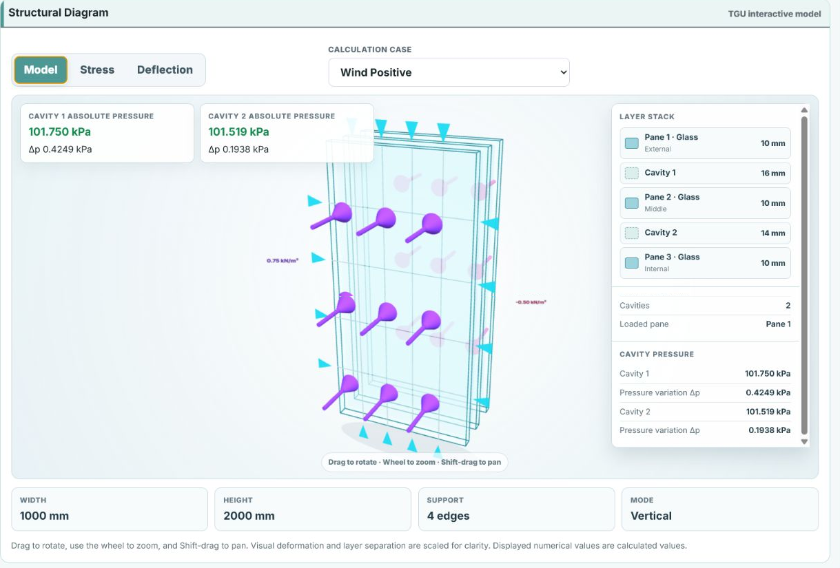
The worked example uses a vertical 1000 × 2000 mm four-edge supported TGU with three 10 mm annealed monolithic panes and 16 mm and 14 mm cavities. The reference cavity state is 101.325 kPa at 20 °C, and the applied 3 s wind actions are +0.750 kN/m² pressure and −0.500 kN/m² suction.
Example Cavity and Pane Distribution
For positive wind, the calculated cavity-pressure increases are 0.425 kPa and 0.194 kPa. The resulting pane pressure components are +0.325, +0.231 and +0.194 kN/m² on Panes 1, 2 and 3. For suction, the pane components are −0.217, −0.154 and −0.129 kN/m² respectively.
Example Governing Result and Interpretation
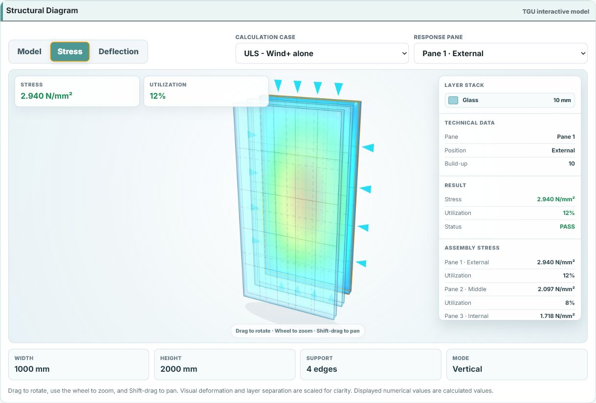
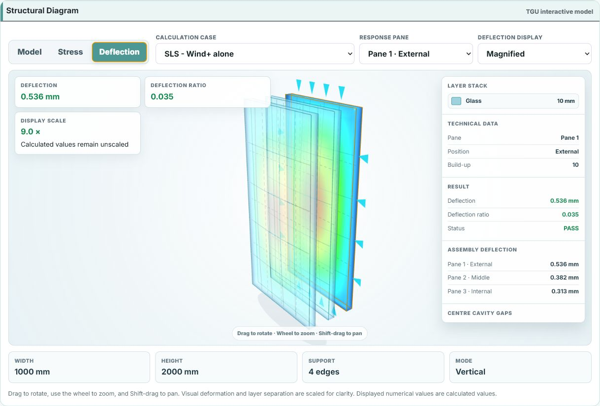
Pane 1 governs both limit states for this input set. The governing ULS case has 2.928 N/mm² stress and 0.117 utilization. The governing SLS case has 0.533 mm deflection against a 15.385 mm limit, giving a ratio of 0.035. Different pane stiffnesses, cavity widths, reference states or actions can change the distribution and governing pane.
Worked Example: TGU Annex C 10 / 16 / 10 / 14 / 10
The calculation uses the implemented rectangular-IGU route from the reviewed 2024 prEN 19100-2 draft.
- Pane size
- 1000 × 2000 mm
- Orientation and support
- Vertical, four edges supported
- TGU build-up
- 10 / 16 cavity / 10 / 14 cavity / 10 mm
- Glass panes
- Three 10 mm annealed monolithic panes
- Reference cavity state
- 101.325 kPa at 20 °C
- Applied wind actions
- +0.750 / −0.500 kN/m², 3 s duration
- Governing combination
- 1.5 Wind
- Design action
- 1.125 kN/m²
- Calculated response
- 2.928 N/mm² stress, Pane 1
- Utilization or ratio
- 0.117 utilization
- Governing combination
- Wind
- Design action
- 0.750 kN/m²
- Calculated response
- 0.533 mm deflection, Pane 1
- Utilization or ratio
- 0.035 of 15.385 mm limit
For positive wind, +0.325, +0.231 and +0.194 kN/m² act on Panes 1, 2 and 3. For suction, the corresponding pane components are −0.217, −0.154 and −0.129 kN/m². Pane 1 governs this input set. Open the EC10 calculator to reproduce or change the inputs.
Annex C Engineering Figures
Conceptual TGU interaction, followed by examples showing load application and the resulting stress and deflection in each pane.
Swipe horizontally to view more figures
Frequently Asked Questions
What does Annex C calculate for an IGU?
Within the implemented rectangular-IGU scope, Annex C is used to evaluate the interaction between pane deformation, sealed cavity pressure and the applied pressure or environmental state.
Does VitraLab support both DGU and TGU?
Yes. The EC10 calculator supports two-pane DGU and three-pane TGU systems with one or two sealed cavities respectively.
Are altitude and temperature effects combined with wind automatically?
No. Optional altitude, pressure and cavity-temperature states are reported separately as Annex C engineering-review states.
Can a laminated pane be used in a DGU or TGU?
Yes. Each pane can be defined independently as monolithic or laminated. Laminated panes retain the applicable action-specific equivalent-thickness and coupling basis.
Why are results reported for every pane?
Cavity interaction and pane stiffness affect load distribution. The governing pane can therefore change between actions, ULS resistance checks and SLS deflection checks.
Is the Annex C implementation based on a final standard?
No. It is based on the reviewed 2024 draft of prEN 19100-2 within VitraLab's validated implementation boundary. The output requires engineering review and does not establish compliance with a final adopted Eurocode.
Engineering content is prepared and maintained by VitraLab Engineering. Worked examples show how the current calculator treats a defined case; they do not replace project-specific verification.