
Overview
- Primary topic
- Structural glass supports
- Engineering basis
- Four-edge support
- Review status
- Project-specific verification required
Why the Support Model Matters
The support model defines which pane edges transfer reaction and which edges remain free. It affects the structural response, governing span, deflected shape and the calculation route available for the pane. The selected model should represent the real framing or fixing arrangement rather than the most favourable result.
Four-Edge Support
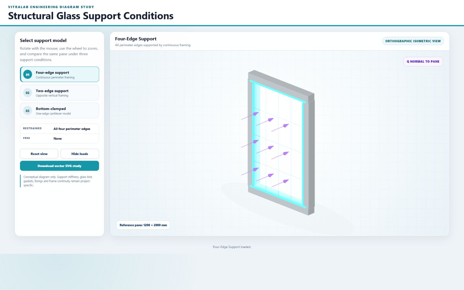
All four perimeter edges are treated as continuously supported. The figure represents edge support around the pane, not a fully fixed connection. Frame movement, glass bite, gasket behaviour and local restraint remain separate project considerations.
Support Models
Two-Edge Support
Two opposite vertical edges are treated as continuously supported while the top and bottom edges remain free. The engineer should confirm that the actual framing provides the assumed continuous reaction and that the free edges are not unintentionally restrained.
Bottom-Clamped Support
The bottom edge is treated as the supporting edge and the pane responds as a cantilever-type model. A complete balustrade or screen design still requires verification of the base shoe or clamps, fixing forces, support stiffness, glass engagement and post-breakage requirements.
Load Direction
The purple arrows represent an action acting normal to the reference pane. They show load direction only and do not represent a calculated pressure magnitude, stress distribution or deflected shape.
Applicability
Model Boundaries
The interactive figure is an engineering explanation, not a calculation result. Pane dimensions are illustrative. Project calculations must use the actual geometry, build-up, loads, support continuity and applicable method coverage.
Interactive Support Model
Structural Glass Support Conditions
Rotate, zoom and compare the same reference pane with four-edge, two-edge and bottom-clamped support.
Four-Edge Support
All perimeter edges supported by continuous framing
Open this tab to load the interactive support model.
Frequently Asked Questions
Does four-edge support mean fully fixed glass edges?
No. The figure shows continuous support along all four edges. It does not claim full rotational fixity or rigid supporting frames.
What is free in the two-edge model?
The top and bottom pane edges are free while the two opposite vertical edges provide the continuous support.
Does the bottom-clamped model verify the base shoe or clamps?
No. The pane support model does not verify the fixing system, support stiffness, glass engagement or post-breakage behaviour.
Are the purple arrows calculated loads?
No. They show the direction of an action normal to the pane and do not represent a calculated load magnitude.
Can every calculation method use every support condition?
No. Method coverage depends on the selected standard, geometry and calculation route. VitraLab reports the available route and any applicable coverage warning.
Engineering content is prepared and maintained by VitraLab Engineering. Worked examples show how the current calculator treats a defined case; they do not replace project-specific verification.